Halls on the outside, generation in the middle
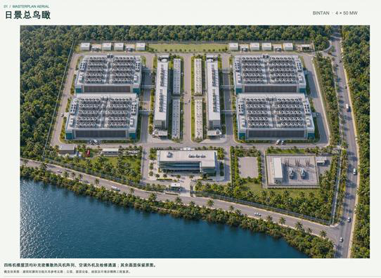
Every hall sits on the perimeter with a short, straight run back to the generator spine. No hall depends on a neighbour for a cable route, so a fault in one hall stays in that hall.
The campus masterplan, the 640MW captive plant, and the 30 million cubic metre reservoir. All three are already built or under construction, so there is no queue and no dependency on external approvals.
Click any numbered block on the masterplan above to see its specification and reasoning.
Daylight view of the Phase 1 plot looking south-west. The four 50 MW halls sit either side of the central diesel spine. The 640 MW captive plant is to the north-west, outside the Phase 1 fence but already built and owned. The reservoir lies 20 m south of the boundary and feeds the tank row.
Short cable trenches, short pipe runs, symmetrical distribution. Every hall sees the same distance to generation, the same water head, the same fibre path to Singapore.
| Element | Quantity | Dimension or rating | Note |
|---|---|---|---|
| Data halls | 4 | 50 MW IT each, 3 floors | Total Phase 1 IT load 200 MW |
| Hall height | 22 m | Clear height 12 m | Headroom for GB300 pipework and roof plant |
| Floor loading | ≥ 20 kN/m² | Raised floor in hall, slab in plant rooms | |
| Transport route | ≥ 25 kN/m² | Ring road, unbroken load path to each hall | |
| Generator buildings | 2 | 80 x 2,500 kW | N+1, centre line between halls |
| Fuel store | 1 | 48 h at full load | Below grade, pumped to day tanks |
| Substation | 1 | 220 kV, dual route | East side, feeds 800 V DC distribution |
| Water tanks | 8 | 1,250 m³ each | 10,000 m³ on site, north edge |
| Water treatment | 1 | Plus fire pump house on the same band | |
| Operations office | 1 | 3 floors | Global NOC and ECC, customer offices |
| Site area, Phase 1 | 30 to 40 ha | Serviced, title clear | No relocation needed |
| Land banked for 3 GW | 1 GW to 3 GW | Expansion from 2029 | Seawater source interface pre-wired |
Every hall sits on the perimeter with a short, straight run back to the generator spine. No hall depends on a neighbour for a cable route, so a fault in one hall stays in that hall.
Building taller once is cheap. Retrofitting a taller hall later, once a liquid cooling loop and overhead busway are already installed, is not. The headroom is there from day one for whatever comes after GB300.
The tank row is a 20 m pipe run from the reservoir through treatment, not 400 m. Gravity helps. The 48 h fuel store is below grade so it does not compete for floor plate.
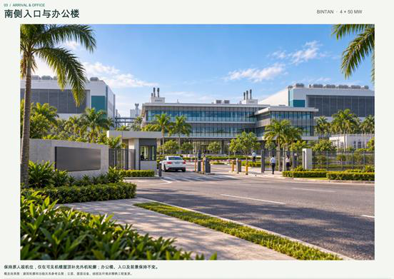
The main gate is on the west side, facing the access road from Galang town. Security checkpoint, vehicle wash, and a covered staging bay for inbound server crates. The operations office looks onto the yard, so the NOC sees every truck that arrives.
Visitor access is controlled to the office and the viewing gallery. The data halls are behind two doors and a biometric reader.
Owned, not contracted. No queue position to hold.
Roughly a third of Singapore commercial power.
Plant to rack. AC distribution lands around 5%.
Written into the lease, with rent credit if we miss it.
800 V DC busway at 1,500 A feeds each hall. Silicon carbide solid-state transformers convert from the 220 kV substation. Transmission loss from plant to rack is 1.8%, compared to roughly 5% for AC.
N+1 diesel fleet with 48 hours of fuel at full load stored below grade. 20 MW / 40 MWh battery store absorbs load steps and provides instant ride-through.
Generation — 80 x 2,500 kW generators, N+1. Each unit can hot-swap without dropping the load.
Switchyard — 220 kV collection, dual route. One route down, one route up, no single point of failure.
Conversion — Solid-state 220 kV to 800 V DC, silicon carbide devices, 98.2% efficiency.
Distribution — 800 V DC busway, 1,500 A per hall, overhead so every tap is visible and maintainable.
Rack entry — PDU shelves drop 800 V to 48 V DC at the rack, N+1 per shelf.
Fuel — Below-grade store holds 48 hours at full load. Day tanks auto-refill from the main store.
Battery buffer — 20 MW / 40 MWh LiFePO4 absorbs load steps, covers generator start-up, provides ride-through.
Testing — Weekly load-bank test, monthly full-load run, quarterly maintenance swap.
Monitoring — DCDC exposes bus voltage, current, and temperature to your DCIM via a read-only API.
Owned. Sitting at the south boundary, 20 m from the fence.
Eight tanks at 1,250 m³, fed from the reservoir.
Annual make-up is 6% to 7% of reservoir capacity.
Zero competition with local residential supply.
The cooling circuit is closed. The only water that leaves the site is water we treat and put back. No withdrawal permits, no competition with agriculture or residential supply.
Beyond 1 GW we switch to seawater source heat rejection using the island's coastal position. That drops fresh water use toward zero.
Size — 30 million cubic metres, 20 m deep, 1.5 km diameter. Enough for 10 years of make-up at current draw.
Treatment — Sand filters, UV, and chemical dosing keep the loop clean. No biofilm, no scaling.
Pumps — N+1 primary pumps, VFD controlled. Redundant suction and discharge headers.
On-site tankage — Eight 1,250 m³ tanks buffer the supply. Each tank has its own pump set and isolation valves.
Fire water — Dedicated fire pump house draws from the same reservoir. 4-hour supply at maximum demand.
Monitoring — Level, temperature, pH, and conductivity exposed via DCIM API.